
 cs
cs
Product Overview The FH80NE-40 is a 40A high-voltage DC relay designed for high-voltage systems in new energy vehicles. It is mainly intended for pre-charge relay and heating relay applications. The product provides 40A continuous current...
Číst více
x


Zakázková výroba Current Sensor Transformer(CT) Výrobci
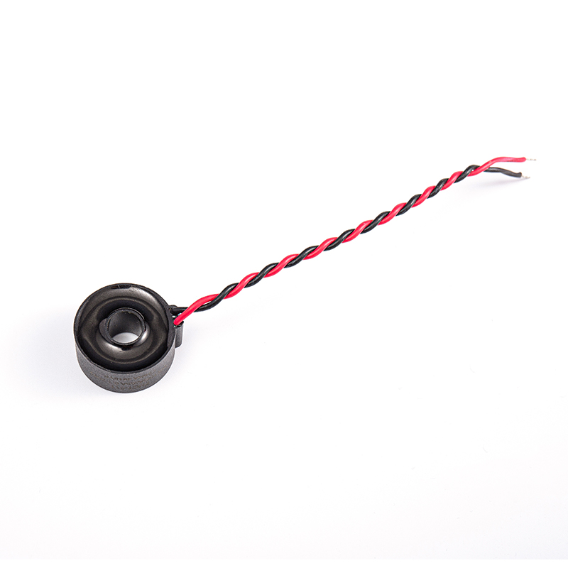
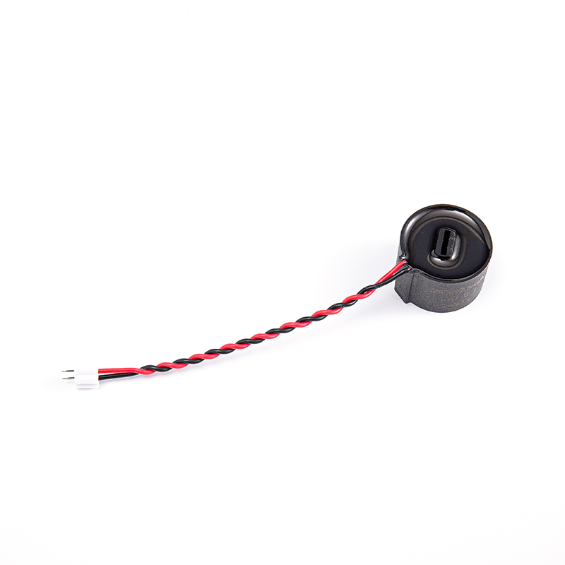
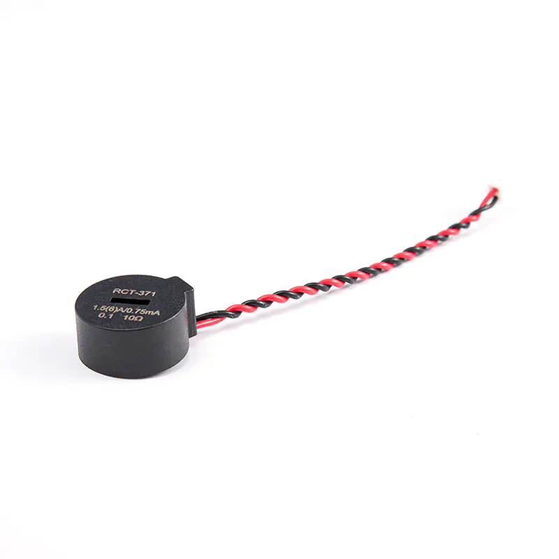
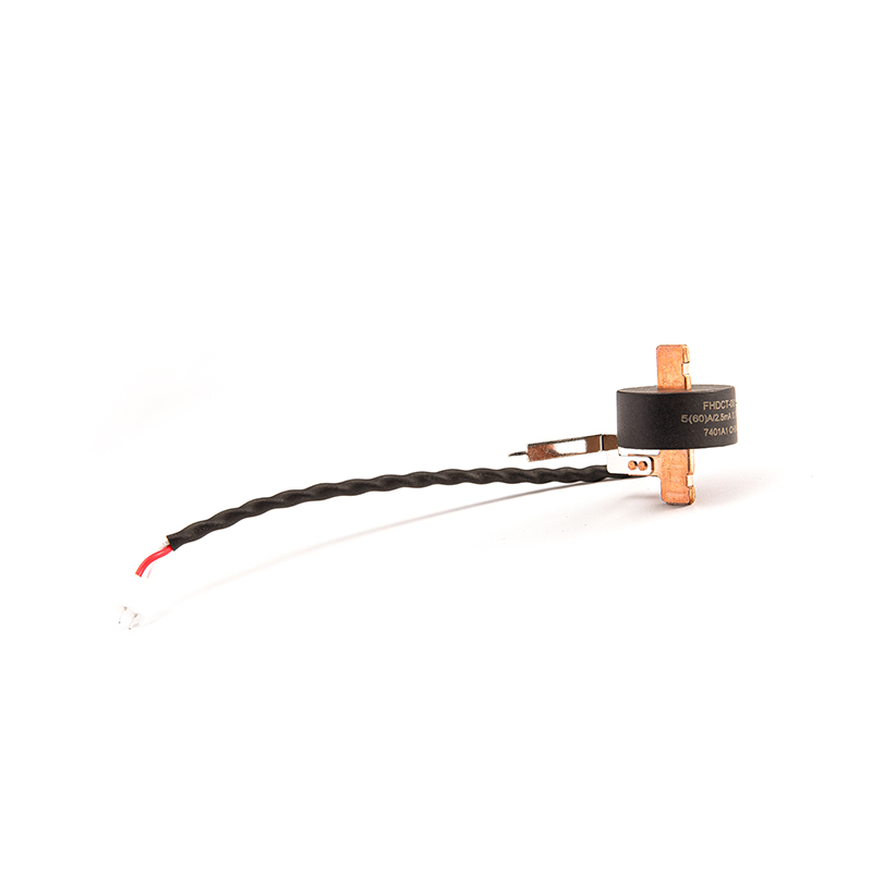
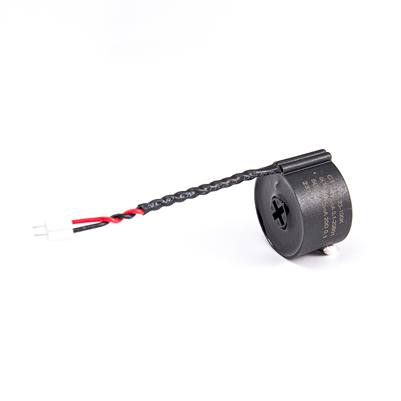
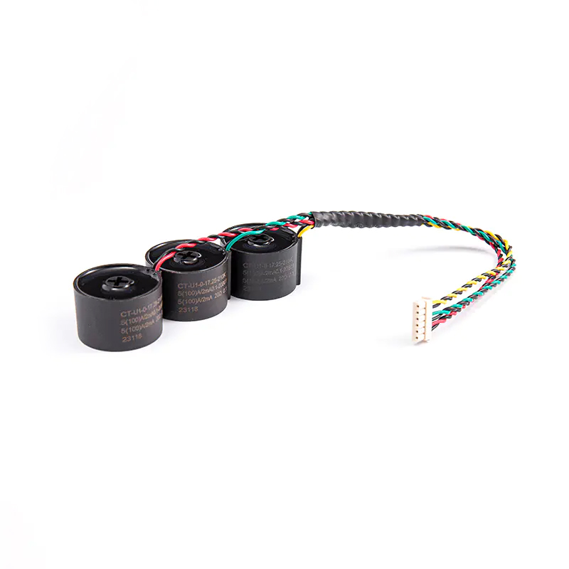
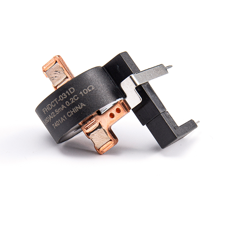
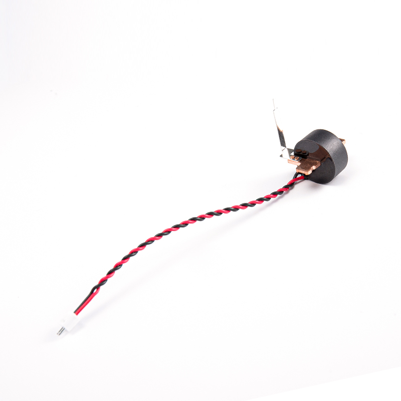
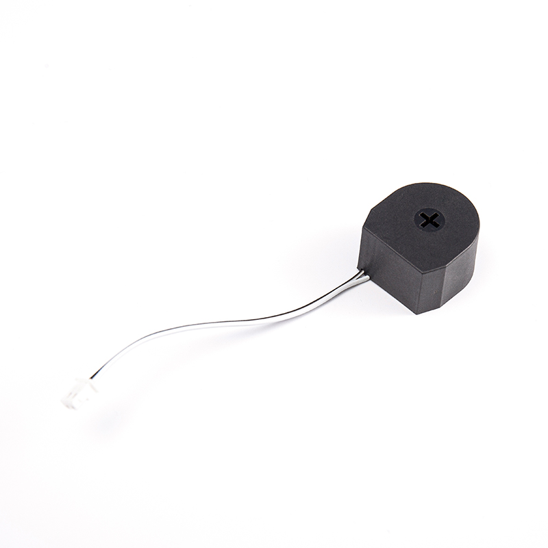
Proudový transformátor (CT) je zařízení používané k měření střídavého proudu. Je široce používán v energetických systémech k zajištění bezpečného a přesného monitorování toku proudu. Převádí velký proud na primární straně na malý proud na sekundární straně pomocí principu elektromagnetické indukce, což je vhodné pro měření, ochranu a řízení. Hlavní funkcí proudového transformátoru je převádět velký proud na malý proud v poměru, aby mohl být měřen pomocí elektrických přístrojů s jednotnými specifikacemi. Poskytuje nejen měřenou hodnotu proudu, ale také hraje roli elektrické izolace v energetickém systému, aby se zabránilo poškození měřicího zařízení a personálu vysokým napětím. Konstrukční řešení proudového transformátoru rovněž klade velký důraz na praktičnost a bezpečnost. Například transformátor proudu s průchozím jádrem měří proud průchodem drátu jeho středovým otvorem. Tento design usnadňuje instalaci a údržbu. Plášť proudového transformátoru je obvykle vyroben z plastových nebo kovových materiálů s dobrými izolačními vlastnostmi a je označen jasnými barvami pro označení jeho účelu a důležitosti.
O nás
Zhejiang Fanhar Electronics Co., Ltd.
Zhejiang Fanhar Electronics Co., Ltd. je Čínská továrna na zakázkové Továrna na snímací transformátory proudu a Měřicí transformátor proudu Výrobci, národní high-tech podnik specializující se na výzkum, vývoj, výrobu a prodej relé. Naše výrobky jsou široce používány v systémech chytré domácnosti, fotovoltaické nové energii, nabíjecích stanicích, chytrých měřičích, průmyslovém řízení a dalších oblastech.
V současnosti máme profesionální tým téměř 500 zaměstnanců a provozujeme 30 plně automatizovaných výrobních linek, přičemž 40 % našich výrobků se vyváží do více než 20 zemí po celém světě. Abychom lépe sloužili našim zákazníkům a uspokojili požadavky trhu, neustále zlepšujeme naše výrobky a výrobní technologie a investujeme 6–8 % ročních tržeb do výzkumu a vývoje a inovací.
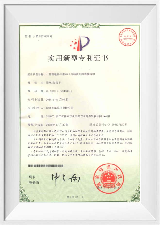
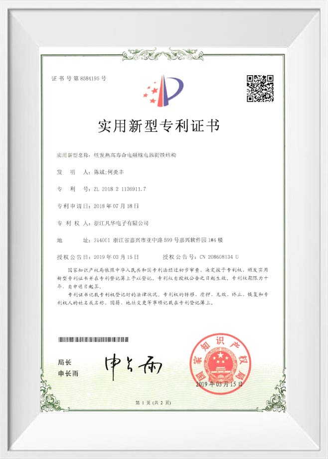
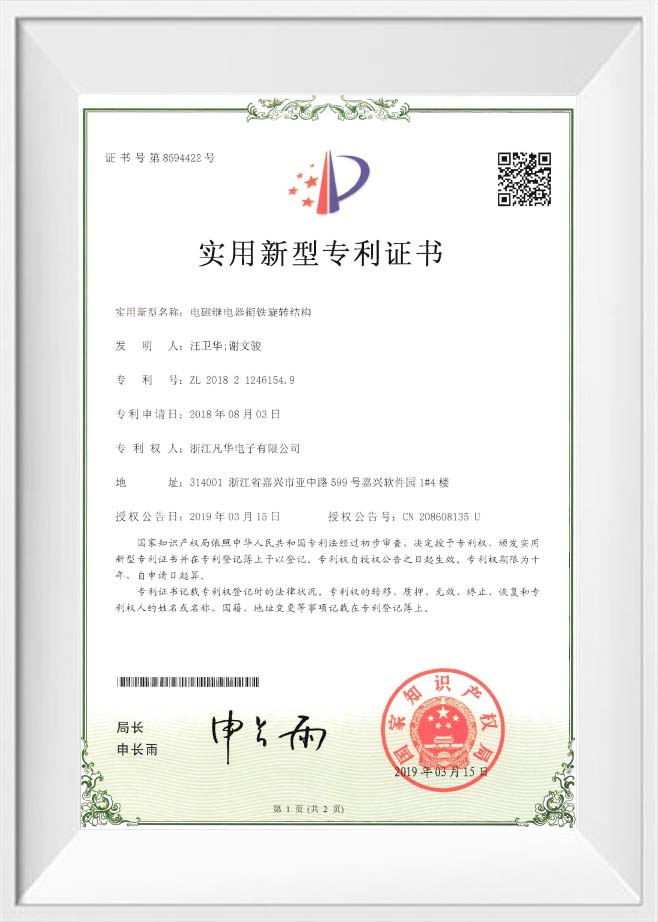
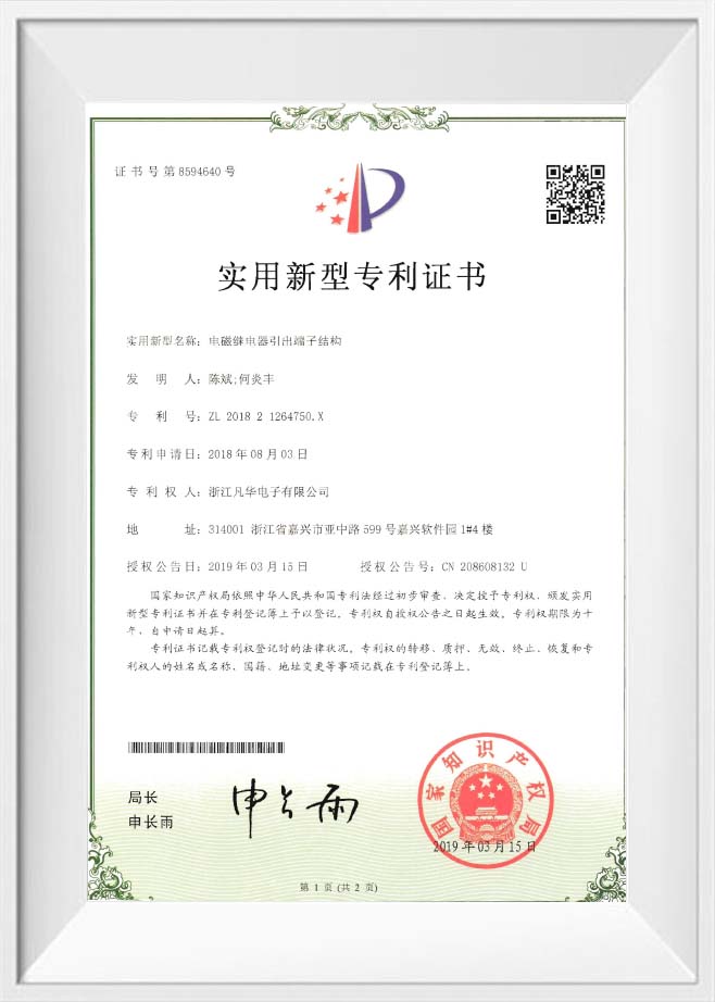
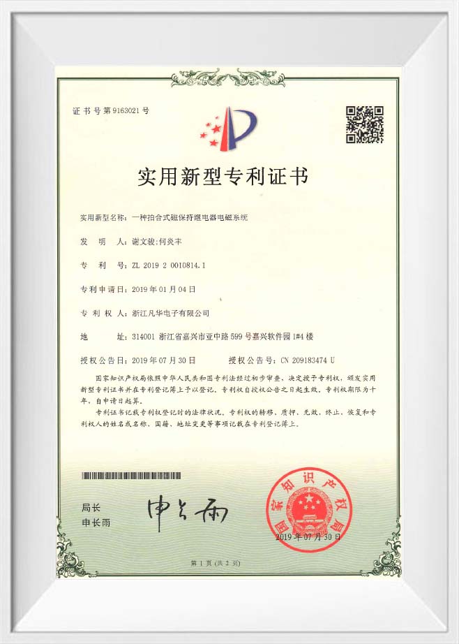
S důrazem na technologické inovace jsme byli uznáni jako národní high-tech podnik a provinční výzkumné centrum a držíme více než 40 národních patentů. Naše výrobky získaly mezinárodní certifikace, včetně ISO9001, ISO14001 a ISO45001, stejně jako autoritativní certifikace UL, TUV a CQC, plně v souladu se směrnicemi EU ROHS/REACH.
Udržujeme 98% míru spokojenosti s dodávkami, naše výrobky slouží globálním lídrům v oboru, jako jsou Huawei, Bull a Eaton, v aplikacích pro chytrou domácnost, průmyslové řízení, novou energii a elektroměry. Do budoucna bude Fanhar Electronics pokračovat v rozšiřování výrobní kapacity a prohlubování naší přítomnosti na trhu s novou energií, a bude usilovat o to, aby se stal poskytovatelem v odvětví relé. Nabízíme Ochranný transformátor proudu na prodej.
Certifikát cti
Novinky
-
-
V době, kdy se rychle rozšiřují nové systémy pro výrobu energie, systémy skladování energie a nabíjecí baterie pro elektromobily, nová energetická relé jako klíčové spínací komponenty v obvodech přímo ovlivňují stabilní provoz ...
Číst více -
S rychlým šířením nové výroby energie, systémů pro ukládání energie a rychlých nabíječek elektrických vozidel hrají výkonová relé – jako kritické spínací komponenty v obvodech – zásadní roli při určování celkové stability zaříz...
Číst více -
Premier Power & Energy Event v jižní Asii – tři představení v jednom s nebývalým rozsahem POWERGEN India 2026 se konal od 1. do 3. září 2026 v Yashobhoomi – IICC v New Delhi v Indii. Tyto tři výstavy, které byly společně ...
Číst více
ČT Oborové znalosti
Mastering Current Sensing & Protection: A Deep Dive into Current Transformer and Current Sensor Transformer
In modern electrical systems—from smart homes to industrial automation and renewable energy—accurate current measurement and reliable protection are non-negotiable. The unsung heroes behind these functions are precision devices like the Current Transformer and its specialized variants. Understanding their distinct roles helps engineers and procurement specialists make informed decisions that enhance safety, efficiency, and system longevity.
1. Fundamental Concepts: Defining the Core Components
While often used interchangeably, Current Transformer (CT), Current Sensor Transformer, Current Measuring Transformer, and Protection Relay CT serve unique purposes. A standard Current Transformer steps down high primary currents to safe, measurable levels. The Current Sensor Transformer integrates signal conditioning for a direct microcontroller interface. The Current Measuring Transformer prioritizes high accuracy over a wide range for billing and monitoring. Finally, the Protection Relay CT is designed to remain linear during fault conditions, ensuring protective relays operate correctly.
- Current Transformer (CT): General-purpose, galvanically isolated sensing.
- Current Sensor Transformer: Embedded electronics for amplified/output signals.
- Current Measuring Transformer: High-accuracy (Class 0.5, 0.2) for revenue-grade metering.
- Protection Relay CT: High saturation knee point, for short-circuit detection.
2. Selection Criteria: Matching the Right CT to Your Application
Choosing between a Current Transformer and a Protection Relay CT depends on your system's priority: measurement fidelity or fault resilience. For energy management systems, a Current Measuring Transformer with 0.5% accuracy is ideal. Conversely, for motor protection relays or grid protection panels, a Protection Relay CT with 5P10 or 5P20 accuracy class is mandatory to avoid core saturation during surges.
2.1 Comparative Overview: Measurement vs. Protection CTs
The table below highlights critical differences when selecting between a standard Current Measuring Transformer and a Protection Relay CT for your next project.
| Feature | Current Measuring Transformer | Protection Relay CT |
|---|---|---|
| Primary Purpose | Billing, power quality analysis | Fault detection, relay tripping |
| Accuracy Class | 0.2, 0.5, 1.0 | 5P10, 5P20, 10P10 |
| Burden Rating | Lower (2.5-15 VA) | Higher (15-30 VA) |
| Core Material | Silicon steel (high μ) | Nickel-iron or advanced alloy |
| Saturation Behavior | Prone to saturation >120% In | Remains linear up to 20-30x In |
3. Technical Deep Dive: Current Sensor Transformer for Modern Electronics
With the proliferation of IoT and smart devices, the Current Sensor Transformer has evolved beyond a simple coil. Modern variants integrate burden resistors, amplifiers, and even analog-to-digital interfaces. This "sensor-ready" design reduces BOM complexity for smart meters, EV chargers, and industrial controllers.
- Output types: Voltage output (0-3.3V, 0-5V) or 4-20mA loop-powered.
- Frequency response: Optimized for 50/60 Hz, but wideband types up to 1 kHz available.
- Key specs to check: Phase angle error (critical for power factor correction) and isolation voltage (typically 3-5 kV).
- Integration tip: Choose a Current Sensor Transformer with built-in shielding to reject external magnetic fields in inverter-dense environments.
4. Application Focus: Protection Relay CT in New Energy & Industrial Control
In photovoltaic systems and charging piles, arc faults and ground overcurrents demand a robust Protection Relay CT. Unlike standard CTs, these devices maintain linearity up to 30 times the rated current, ensuring protection relays receive accurate signals during short circuits. For motor control centers (MCCs), pairing a Protection Relay CT with thermal overload relays prevents nuisance tripping while ensuring fail-safe operation.
- PV Combiner Boxes: Use 5P10 class CTs for string current monitoring plus DC-sensitive residual current detection.
- Charging Piles: Dual-core CTs (measuring + protection windings in one core) save space and reduce costs.
- Smart Meters: Require a current measuring transformer with 0.2S class for bidirectional metering (solar export/import).
5. Installation & Best Practices: Avoiding Common CT Pitfalls
Even a high-quality Current Transformer will fail if installed improperly. Always observe open-circuit secondary rules: never leave a CT secondary open while primary current flows—dangerous high voltages can occur. For Protection Relay CT installations, verify knee point voltage (Vk) is at least 2x the maximum relay voltage under fault conditions. Use shorting blocks for safe disconnection.
- Polarity: Mark P1/P2 (primary) and S1/S2 (secondary). Reversed polarity causes incorrect power readings.
- Burden matching: Exceeding the VA rating of a Current Measuring Transformer increases ratio error by 0.5%-2%.
- Cable length: For secondary leads >10 meters, increase wire gauge to keep loop resistance <25% of rated burden.
FAQ: Your Top Questions on Current Transformers, Protection CTs, and Measuring Sensors
1. What is the difference between a Current Measuring Transformer and a Protection Relay CT?
A Current Measuring Transformer is optimized for high accuracy (0.2–1.0%) at normal operating currents, typically up to 120% of rated primary current. It uses lower saturation cores and is suited for energy metering and power monitoring. In contrast, a Protection Relay CT is designed to maintain linearity under fault conditions (up to 20–30x rated current) with accuracy classes like 5P10 or 10P20. Its core has a higher saturation knee point, ensuring relays operate correctly without distortion. Using a measuring CT for protection can lead to core saturation and relay non-operation during short circuits.
2. How do I select the right Current Sensor Transformer for a microcontroller (e.g., Arduino or STM32) project?
For a direct microcontroller interface, choose a Current Sensor Transformer with built-in signal conditioning. Look for voltage output models (0-3.3V or 0-5V) that match your ADC reference. Key parameters: turns ratio (e.g., 1000:1), output sensitivity (mV/A), and phase error (<1°). Alternatively, select a standard CT plus an external burden resistor and an op-amp circuit. For precision, use a CT with a built-in precision burden and a rail-to-rail output amplifier. Many designs also include a DC offset (e.g., 2.5V for bipolar current sensing).
3. Why does my Current Transformer read zero or low current after installation?
Common causes include: (1) Open secondary circuit — never leave secondary unloaded; always place a burden resistor or shorting block. (2) Incorrect core clamping — split-core CTs must click fully shut; dirt or misalignment reduces coupling. (3) Wrong wiring polarity — swap S1/S2 leads. (4) Insufficient primary current — CTs have a minimum starting current (typically 0.5-1% of rated). (5) Secondary burden too high — reduce cable length or increase wire gauge. Use a clip-on meter to verify that primary current exists before troubleshooting the CT.
4. Can a Protection Relay CT be used for energy measurement?
Technically, yes, but it's not recommended. A Protection Relay CT sacrifices low-current linearity for high fault tolerance. At currents below 5-10% of rated, its error can exceed 2-3%, making it unsuitable for accurate energy billing or power analysis. For measurement purposes, always use a dedicated Current Measuring Transformer (Class 0.5 or 0.2). Conversely, a measuring CT should never be used in protection circuits — it will saturate during a fault, causing protection relays to fail.
5. What certifications should I look for when sourcing a Current Transformer for global markets?
For safety and compliance, demand UL 2808 (US/Canada), IEC 61869-2 (international standard for CTs), and TUV (Europe). For environmental compliance, require RoHS and REACH declarations. In PV and EV charging applications, look for UL 1741 or IEC 62053 for measurement CTs. For Protection Relay CT, verify IEC 61869-2 classes (e.g., 5P10) and optionally VDE 0414. Reputable manufacturers also provide ISO 17025 calibration certificates. Always request test reports for ratio error, phase displacement, and knee point voltage.

- Tel +86-573-82237888
- E-mail [email protected]
- Adresa č. 828, Xinchang Road, Nanhu District, Jiaxing, Zhejiang, Čína
Odkazy
Produkty
